Shortcut Sizing for Air Cooled Heat Exchanger
An air-cooled exchanger is used to cool fluids with ambient air. 1 inch OD tube is the most popular diameter and the most common fins are 1/2 inch or 5/8 inch high. Tube configuration used in this guideline : 1 inch OD tube, 5/8 inch fin height, 10 fins per inch and 2.5 inch triangular pitch.
APSF - External area in ft²/ft² of bundle face area.
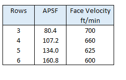
APF - Total external area/ ft of fintube in ft²/ft ~ 5.58.
Face Velocity - Typical air face velocities (VFace ) used in design are tabulated above, these value result in optimum cost of exchanger.
Obtain Process Parameters
Obtain process duty (Q), hot process side inlet (T1) and outlet (T2) temperature. Select an overall heat transfer coefficient (U) from literature based on type of fluids. Select an air inlet temperature (t1) that is not exceeded during a certain percentage of time over the year (e.g. 95% of the time).
Calculate Air Density
Density at air inlet temperature and site elevation
ρo = 14.696 x 29 /(10.7316 x (t1 + 459.67))ρAir / ρo = exp(-29 x z/ (1545 x (t1 + 459.67)))
where,
- t1: Air Inlet Temperature, °F
- z : Elevation above sea level, feet
Calculate MTD
Assume an Air outlet temperature (t2) and calculate LMTD.
LMTD = ((T1-t2) -(T2-t1))/ ln((T1-t2)/(T2-t1))R = (T1 - T2)/(t2 - t1)S = (t2 - t1)/(T1 - t1)
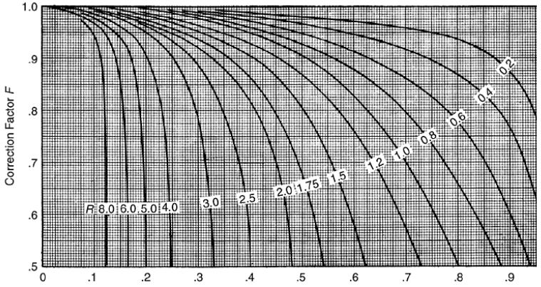
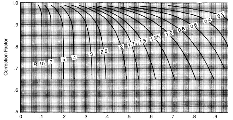
LMTD Correction factor (F) is estimated based on following graphs
Cross Flow Single Pass
Cross Flow Two Pass
Calculate Air Flowrate
Finned area is estimated using following equation :
AFinned = Q / (U * F * LMTD)Bundle Face area is estimated using following equation :
AFace = AFinned / APSFAir Flow is estimated using following relation :
VAir = AFace * VFaceAir Mass flowrate is estimated :
MAir = VAir * ρAirAir temperature rise is calculated :
ΔT = Q / (MAir * CpAir )Revised air outlet temperature is calculated :
t2 = t1 + ΔTThis temperature is again used in above steps to re-estimate air outlet temperature. Above steps are iterated till there is no change in air outlet temperature.
Air Cooler Dimension
Air cooler width is calculated :
W = AFace / LTubeNumber of Tubes are calculated :
NTube = AFinned / (APF * LTube)Number of Tubes per Row are calculated :
Nr Tube = NTube / No of Rowswhere,
LTube : Length of Tube
Air Side Pressure Drop
Air Side pressure drop is calculated as following :
ΔP Total = ΔPStatic + ΔPVelocityStatic Pressure Drop
Pressure drop across tube bundle.
ΔP Static = FP * No of Rows / DRFP = 6*10-8 * ( GFace )1.825
where,
- DR : ρAir / ρAir at seal level and 70°F
- GFace : Air face mass velocity in lb/h.ft² face area
- ΔPStatic : Static pressure drop in inch of H2O
Velocity Pressure Drop
Typically 2 fans are used in air cooler. Fan area per fan (FAPF) is calculated as following :
FAPF = 0.4 * AFace / No. of FansFan Diameter is calculated :
D = (4 * FAPF / π )0.5ΔPVelocity = (ACFM / (4005 * (π* D2/4)) )2* DR
where,
- ACFM : Air flowrate in Actual Cubic Feet per Minute
- ΔPVelocity : Velocity pressure drop in inch of H2O
Power Calculation
Break power for fan is calculated as following :
BHP = ΔP Total * ACFM / 6356 / ηFanMotor power is calculated as following :
Power = BHP / ηMotorResources
- Spreadsheet for Shortcut Air Cooled Heat Exchanger Design
- Web based calculation available at checalc.com
References
- Process Heat Transfer: Principles and Applications,2007, Robert W Serth
- Handbook of Chemical Engineering Calculations, Nicholas P Chopey
- Rules of Thumb for Chemical Engineers, Carl R Branan
- GPSA, Engineering Databook, 12th Edition FPS