Vapor Liquid Separator
Vapor Liquid separators are one of the most common types of process equipment. This article provides step-by-step procedure for two phase vertical vapor liquid separator design. Vapor liquid separation occurs in three stages.
1. The first stage, primary separation uses an inlet diverter so that momentum of the liquid entrained in the vapor causes the largest droplets to impinge on the diverter and then drop by gravity.
2. The next phase, secondary separation is gravity separation of smaller droplets as the vapor flows through the disengagement area.
3. The final stage is mist elimination where the smallest droplets are formed which will separate by gravity.
For secondary separation, maximum allowable vapor velocity is calculated by using the Souders-Brown equation.
\displaystyle \displaystyle V = K\sqrt{\frac{\rho_{L}-\rho_{V}}{\rho_{V}}}
where, ρL, ρV are liquid and vapor densities. K is calculated as following.
\displaystyle \displaystyle K = 0.35 - 0.01\left(P-100\right)/100
where P is in psig, K is in feet/sec. K value is multiplied by a factor of 0.6 for Glycol or Amine solution, 0.7 for compressor suction scrubber, 0.7 for expander inlet separators and 0.5 when there is no mist eliminator.
Vessel diameter is calculated based on vapor velocity V.
\displaystyle \displaystyle D = \sqrt{\frac{4Q}{\pi V}}
where, Q is the vapor volumetric flowrate. For separator with mesh pad, width of support ring is added to diameter calculated above. It varies from 0.3 ft to 1 ft depending on diameter of mesh pad. Clearance of 4 inch is provided around the mesh pad for installation which increases the diameter by 0.66 ft.
Separator Height
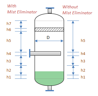
h1 : Low Liquid Level to Bottom Tangent Line
For operating pressure less than 1000 psig (70 barg), it is taken as 6 inch (150 mm) else it is kept 12 inch (300 mm).
h2 : Level Range
It is calculated based on holdup time required and slug capacity of the separator. Holdup volume is calculated based on liquid flowrate multiplied by holdup (residence) time.
\displaystyle \displaystyle h2 = 4\left(V_{Holdup} + V_{Slug}\right)/(\pi.D^2)
Minimum height is taken as 18 inch (450 mm) for proper level control.
h3 : High Liquid Level to Inlet Nozzle
For separator with half pipe at inlet nozzle it is taken as maximum of 0.3D or 12 inch (300 mm).
h4 : Diameter of Inlet Nozzle
This height is taken based on outside diameter of inlet nozzle.
h5 : Inlet nozzle to Mist Eliminator/ Top Tangent Line
For separator without mist eliminator this height is taken as maximum of 0.9D or 36 inch (900 mm). For separator with mist eliminator this height is taken as maximum of 0.45D or 24 inch (600 mm).
h6 : Height of Mist Eliminator
Height of mist eliminator is typically 6 inch (150 mm).
h7 : Mist Eliminator to Top Tangent Line
This height is taken as maximum of 0.15D or 12 inch (300 mm).
All heights are summed up to calculate overall length of separator. L/D ratio is typically kept in the range of 3 to 5. If it is out of this range, new diameter is selected and all above steps are repeated till desired L/D ratio is obtained.
Resources
- Web based calculation available at checalc.com
- Spreadsheet for design sizing of Vapor Liquid Vertical Separator
References
- An article on Souders Brown Equation at Wikipedia