LMTD Correction Factor Charts
Heat transfer rate in the exchanger is represented by
q = U * A * F * LMTDhere F (< 1) is interpreted as a geometric correction factor, that when applied to the LMTD (Log Mean Temperature Difference) of a counter flow heat exchanger, provides the effective temperature difference of the heat exchanger under consideration.
It is a measure of the heat exchanger’s departure from the ideal behavior of a counter flow heat exchanger having the same terminal temperatures. The F-LMTD method is widely used in heat exchanger analysis, particularly for heat exchanger selection, (sizing problems) when as a result of the process requirements the temperatures are known and the size of the heat exchanger is required.
Log Mean Temperature Difference is defined as
LMTD = (ΔT1 - ΔT2) / ln(ΔT1 / ΔT2)where,
ΔT1 = T1 - t2ΔT1 = T2 - t1
T1, T2 are inlet and outlet temperature of Fluid 1; t1, t2 are inlet and outlet temperature of Fluid 2.
Log Mean Temperature Difference Correction Factor F is dependent on temperature effectiveness P and heat capacity rate ratio R for a given flow arrangement. Temperature effectiveness P is different for each fluid of a two fluid exchanger.
For fluid 1, it is defined as the ratio of the temperature range of fluid 1 to the inlet temperature difference.
P1 = ( T2 - T1 ) / ( t1 - T1 )Heat Capacity Ratio R is defined as
R1 = ( t1 - t2 ) / ( T2 - T1 )N (Shell) - 2M (Tube) Pass Tema E
Following general equation is used for shell and tube heat exchanger having N shell passes and 2M tube passes per shell.
S = (R1² + 1)0.5 / (R1 - 1)W = [(1 - P1.R1)/(1 - P1)]1/NF = S.ln(W)/ ln[( 1 + W - S + S.W) /( 1 + W + S - S.W)]
For limiting case of R1 = 1,
W' = (N - N.P1)/( N - N.P1 + P1 )F = 20.5 [(1 - W')/ W' ]/ln[( W'/(1-W') + 1/20.5)/( W'/(1-W') - 1/20.5)]
For plotting the correction factor charts P1 values are listed from 0.01 to 1 with increment of 0.01 and then F values are calculated for each P1 and R1 based on above equations.
For following type of exchangers F values depend on NTU along with P1 and R1, where NTU is defined as number of transfer units. Range of NTU values are listed from 0.01 to 32 and F value is calculated for each value. LMTD Correction factor, F is determined as following -
F = [ 1/(NTU1.(1 - R1))].ln[(1 - R1.P1)/(1 - P1)] ---- (1)For limiting case of R1 = 1,
F = P1 / [NTU1 . (1 - P1)] ---- (2)Cross Flow Fluid 1 Unmixed Tema X
Following relation is used to calculate P1 using NTU.
K = 1 - exp(-NTU1)P1 = [1 - exp(-K.R1)]/ R1
F factor is calculated as per equations (1) & (2).
Cross Flow Fluid 2 Unmixed Tema X
Following relation is used to calculate P1 using NTU.
K = 1 - exp(-R1.NTU1)P1 = 1 - exp(-K/R1)
F factor is calculated as per equations (1) & (2).
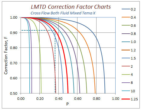
Cross Flow Both Fluid Mixed Tema X
Following relation is used to calculate P1 using NTU.
K1 = 1 - exp(-NTU1)K2 = 1 - exp(-R1.NTU1)P1 = 1/[1/K1 + R1/K2 - 1/NTU1]
F factor is calculated as per equations (1) & (2).
In a similar way, LMTD correction charts can be prepared for different type of geometries based on relation between NTU, P & R.
Resources
- Spreadsheet for LMTD Correction factor charts
- Web based calculation available at checalc.com
References
- Journal of Heat Transfer, Vol. 125, June 2003 - A General Expression for the Determination of the Log Mean Temperature Correction Factor for Shell and Tube Heat Exchangers - Ahmad Fakheri
- Handbook of Heat Transfer 3rd Edition - Chapter 17 - Heat Exchangers by R.K. Shah and D.P. Sekulic