Heat Loss from Insulated Pipe
Heat loss/gain takes place from a pipe carrying hotter/ colder fluid than ambient temperature. Insulation reduces the heat loss to surroundings. Heat loss depends upon number of factors like insulation thickness, ambient temperature, wind speed etc. This article shows how to calculate heat loss from an insulated pipe and a bare pipe to surroundings.
Example
A 3" Carbon steel pipe is carrying hot oil at 180°C and insulated with 50 mm thick calcium silicate insulation. Insulation is cladded with a sheet with surface emissivity of 0.9. Ambient temperature is 28°C and wind velocity is 3.5 m/s. Calculate surface temperature and heat loss from insulated and bare pipe.

Overall heat transfer coefficient of an insulated pipe is defined as following.

where, kPIPE, kINSULATION are thermal conductivity of pipe and insulation. hin is heat transfer coefficient for fluid flowing in pipe and hair is heat transfer coefficient due to air flowing outside the pipe. The first two terms of denominator in above equation are generally smaller compared to remaining terms and can be neglected. For this example first term due to pipe fluid is ignored.
Air Side Heat Transfer Coefficient, hAIR
Air side heat transfer is due to combined effect of convection and radiation. Assume a temperature at cladding surface t_surface and steel pipe surface t_interface. Calculate average air film temperature as following.
t_average = ( t_surface + t_ambient )/ 2Estimate thermodynamic properties of air like thermal conductivity (k), viscosity (μ), expansion coefficient (β = 1/t_average), air density (ρ), kinematic viscosity (ν), specific heat (Cp) and thermal diffusivity (α) at average air film temperature. These properties are available in literature in form of tables, these can be fitted into a polynomial form using excel's LINEST function. Reynolds's number (Re), Prandtl number (Pr) and Rayleigh number (Ra) are calculated based on above properties.
h_radiation
Heat transfer coefficient due to radiation is calculated using following relation.
h_radiation = σ ε (t_surface4 - t_ambient4)/ (t_surface - t_ambient)where σ is Stefan Boltzmann coefficient and ε is emissivity for cladded surface.
h_convection
Convective heat transfer coefficient comprises of forced and free convection. Forced convection can be modeled based on correlation by Churchill and Bernstein.

h_forced = Nu.k_air / D3Free convection is calculated based on correlation by Churchill and Chu.

h_free = Nu.k_air / D3Combined heat transfer coefficient due to forced and free convection is calculated using following relation.
Nu_combined = ( Nu_forced 4 + Nu_free 4) 0.25h_convection = Nu_combined.k_air / D3
Air side heat transfer coefficient is calculated as following.
h_air = h_radiation + h_convectionOverall Heat Transfer Coefficient, U
Thermal conductivity for insulation material and pipe is available in literature and depends upon temperature. It can be fitted into a polynomial equation using LINEST function in excel. Heat transfer resistance due to pipe and insulation is calculated using following relation.
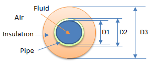
r_pipe = D3.ln(D2/D1) / 2.k_piper_insulation = D3.ln(D3/D2) / 2.k_insulation
Overall heat transfer coefficient is calculated as.
r_overall = r_pipe + r_insulation + 1/h_airU = 1/r_overall
Heat flowing through insulation is estimated.
Q = (t_operating - t_ambient)/r_overallA revised estimate for interface and surface temperature is made.
t_interface = t_operating - Q.r_pipet_surface = t_interface - Q.r_insulation
Above steps are repeated with these new estimates till there is negligible difference in temperature.
Heat loss per unit length of pipe is estimated as following.
HeatLoss = πD3 QBare Pipe
For heat loss from bare pipe all above steps are repeated with resistance due to insulation not considered.
r_pipe = D2.ln(D2/D1) / 2.k_piper_overall = r_pipe + 1/h_air
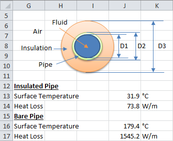
For this example surface temperature and heat loss are as following.

Resources
- Spreadsheet for Heat Loss from Insulated Pipe