Heat Exchanger Rating (Bell-Delaware Method)
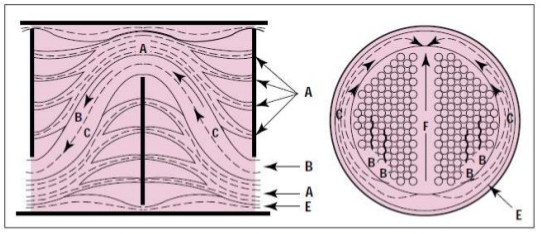
In Bell Delaware method, the fluid flow in the shell is divided into a number of individual streams. Each of these streams introduces a correction factor which is used to correct heat transfer coefficient and pressure drop across the shell. This article gives step-by-step guidance on doing heat exchanger rating analysis based on Bell-Delware method.
Shell Side Heat Transfer Coefficient, hs
Cross flow area, Sm is the minimum flow area in one baffle space at the center of the tube bundle. It is calculated by following equation:
Sm = B[(Ds - DOTL) + (DOTL - Do)(PT - Do)/PT,eff ]where, PT is tube pitch, B is central baffle spacing, DOTL is outer tube limit diameter, Ds is shell diameter and Do is tube outside diameter.
PT,eff = PT for 30° and 90° layoutsPT,eff = 0.707*PT for 45° layout
Shell side cross flow mass velocity, GS is defined as:
GS = mS/Smwhere, mS is shell side mass flow rate. Shell side Reynolds number ReS is then calculated from
ReS = Do.GS / μSwhere, μS is the shell side fluid dynamic viscosity at average bulk temperature.
Shell side Prandtl number PrS is calculated as following :
PrS = CP,S.μS / kSwhere, CP,S is the shell side fluid specific heat and kS is the shell side fluid thermal conductivity.
Colburn j-factor for an ideal tube bank is defined as:
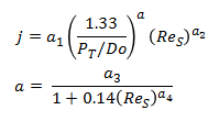
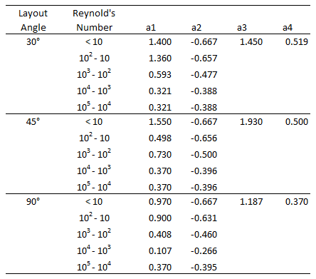
where a1, a2, a3 and a4 are correlation constants listed below.
The ideal tube bank based coefficient is calculated from -
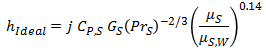
where, μS,W is shell side fluid viscosity at wall temperature.
Correction factor for Baffle Window Flow, JC
The factor JC accounts for heat transfer in the baffle windows. It has a value of 1.0 for exchanger with no tubes in the windows.
JC = 0.55 + 0.72FCFC = 1 - 2FWFW = (θCTL - Sin(θCTL))/2πθCTL = 2cos-1(Ds(1 - 2*Bc/100)/DCTL)DCTL = DOTL - Do
where, Bc is segemental baffle cut in %.
Correction factor for Baffle Leakage, JL
The correction factor JL considers the effects of the tube-to-baffle and shell-to-baffle leakage streams on heat transfer.
JL = 0.44(1-rS) + (1-0.44(1-rS))exp(-2.2rL)rS = Ssb /(Ssb + Stb)rL = (Ssb + Stb)/ SmSsb = Ds*DSB(π - 0.5θDS)Stb = (π/4)((Do+LTB)2 - Do2)Nt(1-FW)θDS = 2cos-1(1 - 2Bc/100)
where, Nt is number of tubes, DSB is diametral clearance between shell & baffle and LTB is diametral clearance between tube and baffle.
Correction factor for Bundle Bypass effects, JB
Bundle bypass correction factor JB accounts for the bundle bypass stream flowing in the gap between the outermost tubes and the shell. The number of effective rows crossed in one cross flow section, Ntcc between the baffle tips is provided by following equation.
Ntcc = (Ds/Pp)(1 - 2Bc/100)Pp = PT 30.5/2 for 30° layoutPp = PT / 20.5 for 45° layoutPp = PT for 90° layout
Ratio of sealing strips to tube rows rss is provided by
rss = Nss/ Ntccwhere Nss is number of sealing strips (pairs) in one baffle.
The bundle bypass flow area, Sb is defind as
Sb = B(Ds - DOTL - Do/2)where, B is central baffle spacing. Correction factor JB is then calculated as following -
JB = exp(-Cj(Sb / Sm)(1 - (2rss)1/3)) for rss < 0.5JB = 1 for rss >= 0.5Cj = 1.35 for ReS < 100Cj = 1.25 for ReS >= 100
Correction factor for adverse temperature gradient, JR
The factor JR accounts for the decrease in the heat transfer coefficient with downstream distance in laminar flow.
Ntcw = (0.8/Pp)(Ds(Bc/100) - (Ds-(DOTL-Do))/2 )NB = 1 + (int)(L - 2Ls - LBIn - LBOut)/BNC = (Ntcw + Ntcc)(1 + NB)JRL = (10/NC)0.18JR = 1, ReS > 100JR = JRL + (20-ReS)(JRL - 1)/80, ReS <= 100, ReS > 20JR = JRL, ReS <= 20
where, L is tube length, Ls is tubesheet thickness, LBIn is inlet baffle spacing and LBOut is outlet baffle spacing.
Correction factor for unequal baffle spacing, JS
n1 = 0.6, ReS >= 100n1 = 1/3, ReS < 100JS = ((NB-1)+(LBIn/B)1-n1 + (LBOut/B)1-n1)/((NB-1)+(LBIn/B) + (LBOut/B))
Shell side heat transfer coefficient is calculated as
hs = hIdeal(JC.JL.JB.JS.JR)Shell Side Pressure Drop, ΔPs
Friction factor for ideal tube bank is calculated as following -
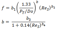
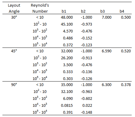
where b1, b2, b3 and b4 are correlational constants listed below.
Pressure drop for an ideal tube bank is calculated from
ΔPIdeal = 2f(GS²/ρS)(μS/μS,W)0.14 NtccCorrection factor for Baffle Leakage, RL
RL = exp(-1.33(1+rS)rLp)p = 0.8 - 0.15(1+rS)
Pressure drop for window section, ΔPW
Following terms are calculated as -
SWG = (Ds²/8)(θDS - Sin(θDS))SWT = Nt.FW(πDo²/4)SW = SWG - SWTGW = mS/(Sm.SW)0.5DW = 4.SW /(π.Do.Nt.FW + θDS.Ds)
Pressure drop for laminar and turbulent flow is calculated.
ΔPW, Turb = NB.RL(2+0.6*Ntcw).GW²/(2.ρS)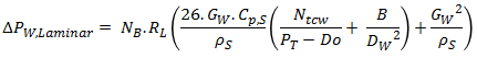
ΔPW = ΔPW, Turb , ReS >= 100ΔPW = ΔPW,Laminar , ReS < 100
Correction factor for Bundle Bypass effect, RB
RB = exp(-Cr(Sb / Sm)(1 - (2rss)1/3)) for rss < 0.5RB = 1 for rss >= 0.5Cr = 4.5 for ReS < 100Cr = 3.7 for ReS >= 100
Correction factor for unequal baffle spacing, RS
n = 0.2, ReS >= 100n = 1.0, ReS < 100RS = 0.5((B/LBIn)2-n + (B/LBOut)2-n)
Pressure drop in Central Baffle spaces, ΔPC is defined as -
ΔPC = (NB - 1)ΔPIdeal.RL.RBPressure drop in entrance & exit baffle spaces, ΔPE is calculated as -
ΔPE = ΔPIdeal(1 + Ntcw/Ntcc).RB.RSShell side pressure drop is calculated as following -
ΔPS = ΔPW + ΔPC + ΔPETube Side Heat Transfer Coefficient, ht
Reynold's number and Prandtl number are calculated as following -
ReT = Di.v.ρt/μtPrT = Cp,t.μt/kt
where, Di is tube inside diameter, v is velocity, ρt is density, μt is viscosity, kt is thermal conductivity and Cp,t is specific heat for fluid on tube side.
For laminar flow, ReT < 2300, Sieder and Tate correlation is used for Nusselt's nubmer.
Nu = 1.86(ReT.PrT.Di/Leff)1/3Leff = L - 2*Ls
For turbulent flow, ReT > 10,000, following equation developed by Petukhov-Kirillov can be used.
Nu = (f/2)ReT.PrT/(1.07+12.7(f/2)0.5(PrT2/3-1))f = (1.58 ln(ReT) - 3.28)-2
For transient flow, Nusselt number can be interpolated from Nu Laminar & Nu Turbulent.
Heat transfer coefficient is calculated as following -
ht = Nu.(kt/Di)(μt/μt, w)0.14Tube Side Pressure Drop, ΔPt
Tube side pressure drop is calculated by following equation -
ΔPt = (4.f.Leff.Np/Di + 4.Np)ρt.v²/2where, Np is number of tube passes.
Overall Heat Transfer Coefficient, U
Resistance due to tube wall is calculated as following
Rtube = Do/(2.ln(Do/Di).ktube)where, ktube is thermal conductivity of tube material. Overall clean heat transfer coefficient, UClean is calculated as per below equation
UClean = 1/(hS + Do/(Di.ht) + Rtube)Overall dirty heat transfer coefficient, UDirty is calculated as per below expression
UDirty = 1/(1/UClean + fshell + ftube)where, fshell & ftube are fouling factors for shell and tube side.
Heat transfer coefficient required, URequired is calculated as following
URequired = Q /(A x LMTDcorrected)where, Q is heat duty, A is heat transfer area and LMTDcorrected is corrected logarithmic mean temperature difference.
Over Surface, % = (UClean/URequired - 1)*100Over Design, % = (UDirty/URequired - 1)*100
Resources
- Web based calculation available at checalc.com
- Spreadsheet for Heat Exchanger Rating based on Bell-Delaware Method
References
- Chapter 4, Design Fundamentals of Shell-And-Tube Heat Exchanger
- Process Heat Transfer - Principles and Applications, 2007 - Robert W. Serth
- Chemical Process Computations, 1985 - Raghu Raman