Pump Sizing Calculation
Pump is a most common equipment used in a chemical plant to transfer fluid from one location to another. This article shows how to do pump sizing calculation to determine differential head required to be generated by pump based on suction and discharge conditions.
Pressure at pump suction is calculated as following
\displaystyle \displaystyle P_{Suction} = P_{1} + P_{Static}-\triangle P_{Equipment}-\triangle P_{Friction}
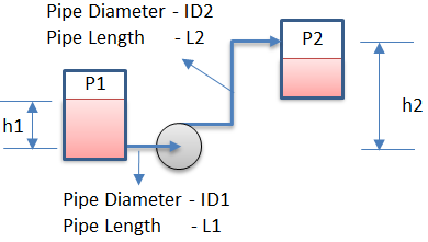
where, P1 is pressure at liquid surface in suction vessel, Pstatic is pressure due to height of liquid level above pump suction, ΔPEquipment is pressure drop in an equipment at pump suction like strainers, filters etc and ΔPfriction is pressure drop due to suction pipe and fittings.
Pstatic
\displaystyle \displaystyle P_{static} (psi) = h1*SG/2.31
\displaystyle \displaystyle P_{static} (bar) = h1*\rho*g/100000
where, h1 is height of liquid above pump suction, SG is specific gravity of liquid, ρ is liquid density (kg/m³) and g is gravitational constant (9.81).
ΔPfriction
\displaystyle \displaystyle \triangle P_{friction} = \triangle P_{Pipe} + \triangle P_{Fittings}
ΔPPipe is pressure drop in a pipe due to single phase fluid flow. ΔPFittings is pressure drop due to pipe fittings, which can be calculated based on 2-K & 3-K method.
Discharge Pressure
Pressure at pump discharge is calculated as following
\displaystyle \displaystyle P_{Discharge} = P2 + P_{Static}+\triangle P_{Equipment}+\triangle P_{Friction}
where, P2 is pressure at liquid surface in discharge vessel, Pstatic is pressure due to height of liquid level above pump suction, ΔPEquipment is pressure drop in equipment at pump discharge like heat exchangers, control valve, flowmeter, valves etc and ΔPfriction is pressure drop due to suction pipe and fittings.
Pstatic
\displaystyle \displaystyle P_{static} (psi) = h2*SG/2.31
\displaystyle \displaystyle P_{static} (bar) = h2*\rho*g/100000
where, h2 is height of liquid above pump suction at which liquid is to be discharged.
ΔPfriction is calculated in similar way as mentioned above for discharge piping.
Differential Head
Differential head required to be generated by pump is calculated as following.
\displaystyle \displaystyle Head (ft) = (P_{Discharge}-P_{Suction})*2.31/SG
\displaystyle \displaystyle Head (m) = (P_{Discharge}-P_{Suction})*100000/(\rho*g)
Hydraulic Power
Hydraulic power is calculated as following.
\displaystyle \displaystyle Power (bhp) = Head(ft) * Flow(gpm) * SG / 3960
\displaystyle \displaystyle Power (kW) = Head(m) * Flow(m³/h) * SG * g / 3600
NPSH Available
Net Positive Suction Head (NPSH) available is calculated as following.
\displaystyle \displaystyle NPSH_{Available} (ft) = (P_{Suction} - P_{Vapor})* 2.31 / SG
\displaystyle \displaystyle NPSH_{Available} (m) = (_{Available})* 100000 / (\rho*g)
where, PVapor is vapor pressure of liquid at suction vessel temperature.
System Head Curve
System head curve is a graphical representation of the relationship between flow and hydraulic losses in a given piping system. It is prepared by calculating differential head as specified above at different flow. The intersection of the pump manufacturer's curve with system curve defines the operating point of the pump.
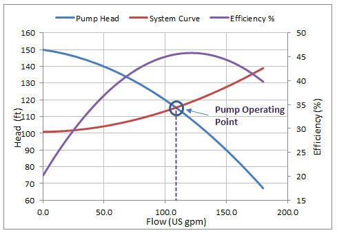
Pump curve and system curve can be fitted into a second order polynomial. Operating point is calculated by solving these equations for positive roots.
Resources
- Web based calculation available at checalc.com
- Spreadsheet for design sizing of Pump Sizing Calculation